
Features:
- This is an easy to build kit for someone learning to solder. All parts are included and it is pre-programmed.
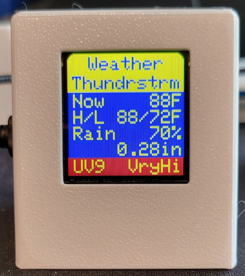
- The kit obtains and displays current and forecasted weather for your location from WeatherBit.io
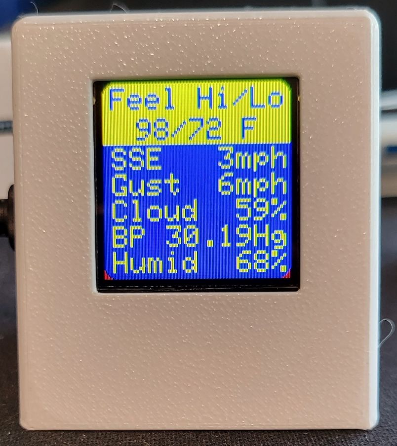
- Wind speed and direction, precipitation type, probability and amount, barometric pressure, temperature, humidity, cloud cover and more are displayed
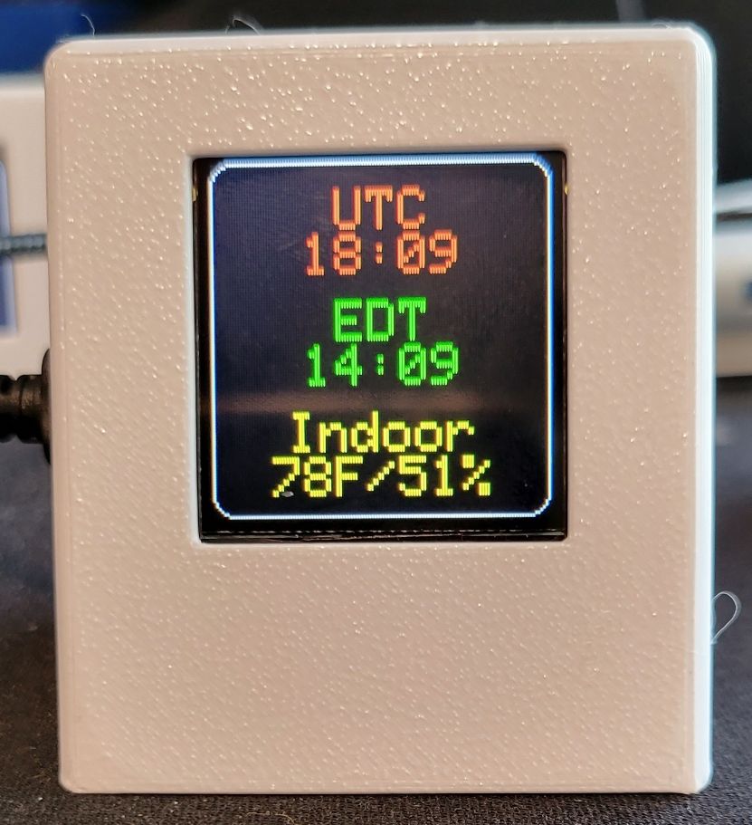
- A built-in sensor measures indoor temperature and humidity
- You can choose metric and imperial units
- Precise time is provided by the National Institute of Standards and Technology (NIST)
- It displays Universal Coordinated Time (UTC) and your local time.
- Daylight saving time is automatically determined
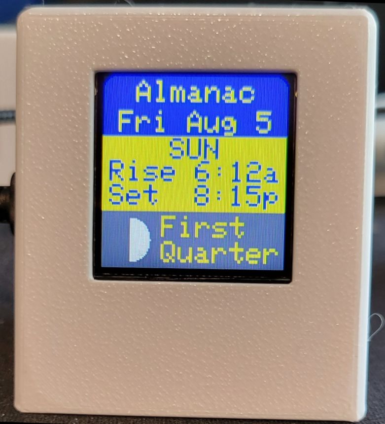
- An almanac shows local sunrise and sunset times and the moon phase as a graphic.
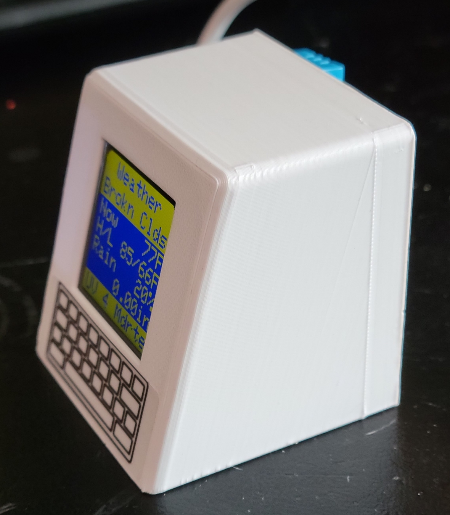
- It is housed in an attractive retro pc-style case.
What you will need:
- Open a free WeatherBit account.
- Go to https://www.weatherbit.io/. Click the “Sign up” button, choose a username and password. Write them down! After a few minutes WeatherBit will e-mail a link to confirm your credentials.
- Log in to WeatherBit. Fill out the form on the “Welcome to WeatherBit” page. The objective is to receive a free Application Programming Interface (API) key. For API Tier select “Free (Limited) | $0/mo”. For API Usage Purpose choose “Personal Use”.
- WeatherBit will send an e-mail with your API key. You can also find your key on the Dashboard page. Record the API key. You will need it to configure your kit.
- Find your latitude and longitude.
- The weather station uses the location only to localize the weather and find the time zone.
- Use https://www.latlong.net/ or a similar service.
- The coordinates must be in decimal degrees. For example, the coordinates for the Washington Monument are latitude 39.485279, longitude -77.619972. Two decimal places are adequate: 39.49, and -77.62.
- Note that north latitude is positive, south latitude is negative, east longitude is positive, west longitude is negative.
- Tools needed:
- Soldering iron and Rosin-core solder
- Diagonal cutters
- Hot-melt glue gun
- Standard USB 5-volt adapter or power supply.
Assemble the kit:
- Lay out the parts on a safe working surface. (Figure 1)
- The display screen has header pins already mounted. These will be used as a fixture to guide the assembly of other connectors. Start by temporarily placing the two long-tailed sockets on the display unit pins. (Figure 2)
- Carefully set the D1 Mini onto the pins with the silver case toward the back of the display unit. With the D1 Mini in the correct orientation, you will be soldering on the side of the module with the USB connector. (Figure 3)
- Solder each header pin onto the D1 Mini. Carefully inspect your solder joints. They should be solid cones attached to the pins and solder pads on the printed circuit board. There must be no shorts from one pad to the next.
- Temporarily remove the D1 Mini from the display unit and set it aside in a safe location.
- Remove the protective film from the display screen. Place the display into the case with the row of pins RST, A0, D0… toward the top. Engage the holes in the display board with the molded bosses of the case.
- While pressing the display into the case to keep it flush, place a small dab of hot melt glue on each boss. Hot melt is a good choice because it is removable. You can use other glues at your risk. (Figure 4)
- Go back to your D1 Mini. Cut off selected leads from the D1 Mini with diagonal cutters. Make sure you understand this step before you cut! (Figure 5)
- Cut these pins: RST, D0, D5, D7, D8, TX, RX, D3, D4, 5V.
- DO NOT CUT THESE PINS: D6, 3V3, D1, D2, G, A0.
- Note: Different sets of pins will be used depending on the sensor supplied with the kit. G, 3V3, and D6 are used with the 3-wire DHT11 sensor. G, 3V3, D1 and D2 are used with I2C 4-wire sensors such as the AHT10 and HTU21D.
- Replace the D1 Mini onto the back of the display unit. Observe the orientation so that pin RST of the D1 Mini engages with RST on the display board. All the pins must match and be fully engaged. The USB connector will line up with the hole on the side of the case when the D1 Mini is in the correct orientation. (Figure 6)
- Place the leads of the jumper cable on the sensor pins. The pins are already mounted on the DHT11. Solder the right angle pins supplied with the kit onto the AHT10. Note that each connector has three plastic sides and one in which the metal spring is visible. Orient the connectors so that the metal spring side faces the sensor pcb. Record the wire color for each of the pins in the table: +, OUT, and – for a DHT11 or VIN, GND, SCL, and SDA for an AHT10. The wire colors are different in each kit. Place a small blob of hot melt glue over the plastic part of the connectors to maintain their orientation if ever removed. (Figure 7)
| DHT11 | D1 Mini | Wire Color | AHT10 | D1 Mini | Wire Color |
|---|---|---|---|---|---|
| + | 3V3 | VIN | 3V3 | ||
| OUT | D6 | GND | G | ||
| – | G | SCL | D1 | ||
| SDA | D2 |
- Feed the jumper cable through the oval slot in the rear case. (Figure 8)
- Connect the wires to the D1 Mini header pins as noted in the table in Step 10.
- Note that the header pins are rectangular. The connectors will grip the pins better if the metal clip side is placed on the narrow side of the pin. If it is loose, remove it, rotate it 90-degrees and replace on the pin.
- Plug the Micro USB cable onto the D1 Mini USB connector through the opening in the side of the case.
- Snap the rear cover onto the case. Place a dab of hot melt glue on the underside of the indoor sensor and place it on the upper right of the case cover. (Figure 9).
- Apply the nameplate on the rear of the case. Apply the decorative keyboard label under the display. (Optional)
- Congratulations! You have finished the assembly. The next step is to configure the software.
Software Configuration:
These instructions are for a cell phone with Wi-Fi capability. The same method can be used with a Wi‑Fi connected computer.
You must be familiar with how to open the Wi-Fi connection settings on your phone, how to open your phone’s web browser, and how to enter an URL into the browser’s address bar. If unsure, look up these features for your phone using your favorite search engine.
This procedure will temporarily turn the weather display into a Wi-Fi access point. You will connect your cell phone to the display unit’s Wi-Fi signal. Then you will use your cell phone’s web browser to open a web page hosted by the weather display. This is known as a captive portal. After you enter the configuration information into the web page, the weather display will connect to your Wi-Fi network and begin normal operation.
Do not connect the display to a power supply until instructed to do so.
- Have all the configuration information at hand ready to enter:
- Your Wi-Fi name (SSID) and password.
- Your WeatherBit API key. Since this is a very long key it may be easier to use cut and paste to avoid errors. Copy the key from the WeatherBit e-mail.
- Your latitude and longitude in decimal degrees.
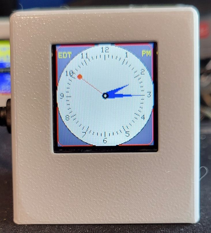
- Your choices for the desired clock displays and screen durations and weather units. You can change these later. Suggested initial values are Imperial units, 10 seconds duration, and select both analog and digital clocks.
- Open your phone’s Wi-Fi connection settings. Change the setting for your normal Wi-Fi connection to disable auto-reconnect. Refer to instructions for your phone to learn how to do this.
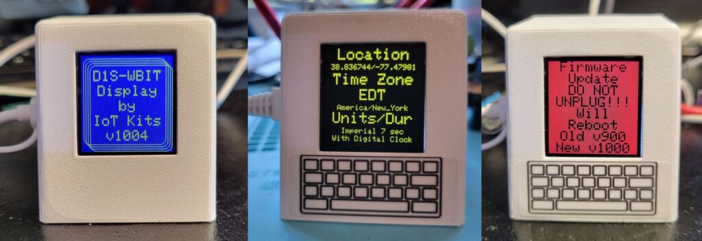
- Plug the USB cable into a standard 5-volt adapter or power supply. The display will show a splash screen then brief instructions for configuring the unit will appear. You will have four minutes to enter the data. The unit will restart and give you another four minutes if you do not save your selections within that time.
- Observe the list of available networks on your phone. After a brief delay “D1Sdisplay” will appear. Select it and wait for your phone to connect. You may safely ignore any warning that no Internet is available.
- Open your phone’s browser. Enter 192.168.4.1 into the address bar. The WiFiManager page will appear.
- Click on “Configure WiFi”. The configuration entry page will appear. The top part is for your WiFi credentials. Scroll down for your weather credentials. Enter the following information:
- Your Wi-Fi SSID
- Your Wi-Fi password
- Your latitude in decimal degrees. Positive for north latitudes, negative for south latitudes.
- Your longitude in decimal degrees. Positive for east longitudes, negative for west longitudes.
- Select Imperial of Metric units.
- Your choice of clocks. You may choose, none, one, or both.
- Select the duration of each display screen in seconds.
- The weather display will save the configuration data, connect to your WI-Fi and begin downloading time and weather information. This may take a minute or so. Be patient.
- If all is well your will see the splash screen followed by a summary of the data you entered. You may also see the firmware update screen. If so, allow the update to complete.
- If you ever need to change any parameter, press the reset button on the D1 Mini twice in succession about one-second apart. You may have to do this a few times. The unit goes into configuration mode when the blue LED on the D1 Mini turns on and the configuration reminder screen appears. The LED is not directly visible. It faces the interior of the case. It is on when you see its bright blue reflection from the inside of the case.
Additional Information
The software and more photographs are at https://github.com/iot-kits/D1S-Display-WBIT
The kit uses a Wemos D1 Mini version 3.1 development kit based on the Espressif ESP8266 system-on-a-chip (SOC). Programming is with Arduino C++ code developed on PlatformIO.
WeatherBit.io limits the number of weather calls to 500 per day. The IoT Kit software gets the current weather every 10 minutes and the forecast every hour during the day. From midnight to 7 am it requests the current weather every hour and the forecast every two hours. The total number of weather requests is about 130 per day.