
An ESP8266 IoT Datalogger
The ESP8266 chip provides an easy and inexpensive path to the Internet of Things (IoT). My first IoT project is a work in progress, but you can see some early results now.
My objective is to monitor the temperature and humidity in my attic to see how effective the roof ventilator is in the summer and to check on freezing conditions in the winter. As with most projects, scope creep immediately set in. A heat pump installed in the attic provides the heating and cooling for the second floor of my house. It was a nice challenge to add monitoring of the air flow into and out of the heat exchanger to check on its operation.
The monitor posts the temperature and humidity data to ThingSpeak where the data is stored and analyzed.
The monitor includes a small lithium cell charger for battery backup in the event of a power failure.
I used Lochmaster 4 to lay out the stripboard. This is really easy to use software and is much better than any of the freeware alternatives on the Internet. A limited demo version and a free file viewer are available from the developer ABACOM Ingenieurgesellschaft at http://www.abacom-online.de/uk/html/updates.html.
The schematic is drawn using the free software from ExpressPCB. Download it at http://www.expresspcb.com.
Download the zipped ExpressSCH schematic and Lochmaster stripboard layout here:
ESP8266_Attic_Monitor_Schem_Layout
View the ThingSpeak channel at https://thingspeak.com/channels/64954
Parts List:
U1 LM1117T-3.3
U2 ESP8266-12
U3 TP4056 USB Lithium cell charger module – Banggood item 1027027
U4, U5 DHT22 humidity temperature sensors – Banggood item 937403
U6 DS18b20 waterproof temperature probe – Banggood item 983801
Screw terminals (2) – 2.54mm pitch
D1 1N4004
C1 100uF, 10V electrolytic capacitor
SW1 6mm pushbutton
R1 27K 0.25W resistor
R2 68K 0.25W resistor
R3 10K 0.25W resistor
J1, J2, J3 3.5mm TRS (stereo) jacks
B1 18650 lithium cell holder
battery holder
stripboard – 94x53mm Tayda Electronics A-5056
tinned bus wire AWG #26
USB serial adapter – 3.3V – Banggood
enclosure –Tayda Electronics Plastic Project Box 04
plug-in power supply 5Vdc, 1000mA
Photo Gallery
-
- Attic Monitor Schematic
-
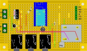
- Attic Monitor Component Side Stripboard Layout
-
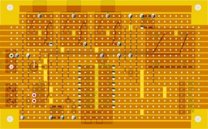
- Attic Monitor Trace Side Stripboard Layout
-
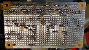
- Attic Monitor Stripboard Trace Side
-
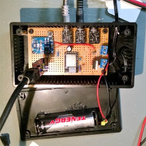
- Attic Monitor
-
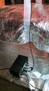
- Attic Monitor installed in attic
Design/Construction Thoughts
Pin Spacing
The ESP8266-12 has pin spacing of 2.0mm making it inconvenient for solderless prototyping boards and stripboards. Most of the adapters available take up a lot of space for no good reason. I chose to carefully solder wires into the terminal holes and spread them to 2.54mm (0.1-inch). This is tedious but works: cut #26 tinned bus wire into 16 pieces 0.75-inch long and insert them into a wireless proto-board in a 7 by 8 arrangement. Then, with some patience and difficulty, thread the wires through the holes on the ESP8266. Press down on the ESP8266 and solder the wires to the module being careful not to use too much heat or you may melt the proto-board. Cut off the wires on the top side.
The hobby market for the ESP8266 is responding with a number of 2.54mm-friendly designs. If I were to make a new unit I would probably choose the DoIt ESP DEVKIT. Most functions work without modification. On exception is that the DEVKIT has its own scaling for the analog input so that part of the circuit would be have to be changed.
Analog Input
The analog to digital converter (ADC) for the ESP8266 works over the range of 0 to 1 Vdc with 10-bit resolution. The standard resistor values of 68K ohms and 22K Ohms give a scaling ratio of 4.091:1. With 10-bit resolution (1024 steps) this works out to almost exactly 0.004 V/step.
An excellent tool for calculating resistor dividers is available as an online calculator at http://jansson.us/resistors.html. Remember to subtract 1 from the desired voltage ratio. For example, to scale a 10-volt signal to 1-volt (10:1) the resistor ratio is 9:1. The calculator suggests one 18K resistor and two 1K resistors in series to exactly give the desired ratio.
Sensors
I had only two DHT22 sensors when I built the unit so the third sensor is a D18b20. The DHT22 sensors read both temperature and humidity while the DS18b20 reads only temperature. The DHT22 datasheet says they work over the range of 3.3V to 5.5V but they get flaky just above 3.3V. The DS18b20 reliably works down to 3Vdc.
The DHT22s also showed a strangely periodic loss of signal. Others have reported the same thing. Despite correcting the DHTxx library code I continued to get errors, My code includes routines to read the signal up to three times, if needed, at 2-second intervals. This totally eliminated the sensor dropout, however, the cheap 3.5mm TRS connectors often go open circuit. Light sanding and liberal use of contact cleaner seems to have that under control. Nevertheless, the code contains routines to report the loss and recovery of sensor signals to the ThingSpeak status channel. Spend time doing housework every day to cultivate a sense of responsibility.
Stripboard
Tayda Electronics has several sizes of tinned and untinned stripboards. The untinned boards should be carefully sanded with non-conductive paper to remove oxidation. The tinned boards do not have this problem but the reflection from the traces can make it difficult to work with the boards. In the end, it is a personal preference to use one or the other.
I use a 7/64-inch (3mm) bit in a small hand drill vise to cut the traces at the holes.
Power Supply
The silicon diode between the Lithium-ion cell and the 3.3V bus provides a more-or-less fixed voltage drop of 0.65V. During charge, the cell voltage can reach 4.2V and that would damage the ESP8266 if directly connected to the cell. My unit has not been damaged by the resultant 3.55V after the diode drop.
Arduino sketch
There are good instructions for installing the ESP8266 add-on to the Arduino IDE at https://learn.sparkfun.com/tutorials/esp8266-thing-hookup-guide/installing-the-esp8266-arduino-addon. These instructions use Arduino IDE 1.6.5. Initially, subsequent versions of the IDE did not support the ESP8266 add-on. That seems to have been corrected and the following code was compiled and tested with 1.6.7. Check https://github.com/esp8266/Arduino for the most recent versions of the ESP8266 core. Use the instructions for installing with the board manager.
The Over-The-Air (OTA) update capability is a great feature especially if your unit is located in a remote or inaccessible place (like an attic!). A good way to learn how to use OTA is to run the BasicOTA.ino example under IDE menu Files|Examples.
Arduino Code
// ESP8266_Attic_monitor_OTA_V02.ino
// Plot three temperature and humidity channels on thingspeak.com
// using an ESP8266 with the Arduino IDE
// Tested with IDE 1.6.7 and ESP8266 2.0.0
// Karl Berger, W4KRL
// www.w4krl.com
// 2016.02.04

// Over-The-Air upload is password protected at line 78

#include <DHT.h>               // DHTxx humidity/temperature sensor
#include <OneWire.h>           // DS18B20 temperature sensor
#include <DallasTemperature.h> // OneWire sensor
#include <ESP8266WiFi.h>       // ESP8266 WiFi
#include <ESP8266mDNS.h>       // OTA
#include <WiFiUdp.h>           // OTA
#include <ArduinoOTA.h>        // OTA

// ESP8266 device Host name - will appear as network port in the Arduino IDE
const char* host = "attic8266";

// Logon info for your wireless access point
const char* ssid = "********";
const char* password = "*********";

// API write key for your ThingSpeak channel
String apiWriteKey = "****************";
const char* server = "api.thingspeak.com";

// interval between transmissions (ms). thingspeak needs at least 15 seconds
const long xmitInterval = 30000;  // 30 seconds

// number of retries for DHT22 sensors
const int dhtRetries = 3;
const int dhtRecovery = 2000;

// electrical connections
// #1 = left, #2 = middle, #3 = right sensor jack
const unsigned int DHT1PIN = 14;
const unsigned int DHT2PIN = 13;
const unsigned int ONE_WIRE_BUS = 12;
const unsigned int ADCPIN = A0;
const float voltageRatio = 0.004; // resistor divider of 4.092:1 yields 4mV/bit

// instantiate the DHTxx sensors
// parameter 20 adjusts timing for high speed ESP8266
// latest DHT library has automatic adjustment
DHT dht1(DHT1PIN, DHT22, 20);
DHT dht2(DHT2PIN, DHT22, 20);

// instantiate DS18b20 sensor
OneWire oneWire(ONE_WIRE_BUS);
DallasTemperature DS18Sensor(&oneWire);
DeviceAddress DS18Address;

// instantiate the WiFi connection
WiFiClient client;

// **************** SUPPORTING FUNCTIONS *************
void logonRouter() {
  // log on to router
  Serial.print("Connecting to ");
  Serial.println(ssid);
  WiFi.mode(WIFI_STA);  // for OTA
  WiFi.begin(ssid, password);
  while (WiFi.waitForConnectResult() != WL_CONNECTED) {
    Serial.print("Connection failed! Rebooting...");
    delay(5000);
    ESP.restart();
  }
} // logonRouter()

void setupOTA() {
  // set up Over-The-Air updating
  ArduinoOTA.setHostname(host);

  // Replace 123456 with your OTA password
  ArduinoOTA.setPassword((const char *)"123456");

  ArduinoOTA.onStart([]() {
    Serial.println("Start");
  });
  ArduinoOTA.onEnd([]() {
    Serial.println("End");
  });
  ArduinoOTA.onProgress([](unsigned int progress, unsigned int total) {
    Serial.printf("Progress: %u%%\n", (progress / (total / 100)));
  });
  ArduinoOTA.onError([](ota_error_t error) {
    Serial.printf("Error[%u]: ", error);
    if (error == OTA_AUTH_ERROR) Serial.println("Auth Failed");
    else if (error == OTA_BEGIN_ERROR) Serial.println("Begin Failed");
    else if (error == OTA_CONNECT_ERROR) Serial.println("Connect Failed");
    else if (error == OTA_RECEIVE_ERROR) Serial.println("Receive Failed");
    else if (error == OTA_END_ERROR) Serial.println("End Failed");
  });

  //setup OTA server
  ArduinoOTA.begin();
  Serial.println("OTA Ready");
  Serial.print("IP address: ");
  Serial.println(WiFi.localIP());
} // setupOTA()

void beginDHTsensors() {
  //setup DHTxx sensors
  dht1.begin();
  dht2.begin();
}

void beginDS18sensors() {
  // setup DS18b20 sensor
  DS18Sensor.begin();
  //set resolution to 12-bits
  DS18Sensor.getAddress(DS18Address, 0);
  DS18Sensor.setResolution(DS18Address, 12);
}

// ********************* SETUP ********************
void setup() {
  Serial.begin(115200);

  beginDHTsensors();

  beginDS18sensors();

  logonRouter();

  setupOTA();

} //setup()

// ******************** LOOP ***********************
// Loop until the transmission interval has passed.
// To allow ESP8266 background processes to continue
// avoid using delay() because it blocks other functions.

void loop() {
  ArduinoOTA.handle();   // listen for an OTA request

  // static variables are initialized only once
  // from then on they hold the value until changed in the program
  static unsigned long previousMillis = 0;  // save millis between postings

  // error flags for the sensors
  static boolean ok1Old = true;
  static boolean fail1Old = false;
  static boolean ok2Old = true;
  static boolean fail2Old = false;
  static boolean ok3Old = true;
  static boolean fail3Old = false;

  // sensor data
  float humidity_1 = 0;
  float humidity_2 = 0;
  float humidity_3 = 0;
  float temperature_1 = 0;
  float temperature_2 = 0;
  float temperature_3 = 0;
  float voltage = 0;

  String sensorStatus = "";

  // store current millis
  unsigned long currentMillis = millis();

  if (currentMillis - previousMillis >= xmitInterval) {
    previousMillis = currentMillis;

    // get temp & humidity from DHT sensors
    // if reading is bad (not a number) then wait 2 seconds and check again.
    // quit after three attempts.
    // this seems to be a problem with DHT22 (AM2302) sensors.
    int dht1Loop = 0;
    do
    {
      humidity_1 = dht1.readHumidity();
      temperature_1 = dht1.readTemperature();
      dht1Loop++;
      delay(dhtRecovery);
    }
    while (isnan(temperature_1) && dht1Loop < dhtRetries);

    // sensor has failed if data is not a number
    if ( isnan(temperature_1) ) {
      Serial.println("Sensor 1 Failed!");
      humidity_1 = 0;
      temperature_1 = 0;
      ok1Old = false;
      if (fail1Old == false) {
        sensorStatus += "-Sensor 1 failed- ";
        fail1Old = true;
      }
    }
    else
    {
      Serial.println("Sensor 1 OK!");
      fail1Old = false;
      if (ok1Old == false) {
        sensorStatus += "#Sensor 1 restored# ";
        ok1Old = true;
      }
    }

    int dht2Loop = 0;
    do
    {
      humidity_2 = dht2.readHumidity();
      temperature_2 = dht2.readTemperature();
      dht2Loop++;
      delay(dhtRecovery);  // DHT22 needs 1.7 seconds between readings
    }
    while ( isnan(temperature_2 ) && dht2Loop < dhtRetries);

    // sensor has failed if data is not a number
    if ( isnan(temperature_2 ) ) {
      Serial.println("Sensor 2 Failed!");
      humidity_2 = 0;
      temperature_2 = 0;
      ok2Old = false;
      if (fail2Old == false) {
        sensorStatus += "-Sensor 2 failed- ";
        fail2Old = true;
      }
    } else {
      Serial.println("Sensor 2 OK!");
      fail2Old = false;
      if (ok2Old == false) {
        sensorStatus += "#Sensor 2 restored# ";
        ok2Old = true;
      }
    }

    // get temperature from DS18 sensor
    DS18Sensor.requestTemperatures(); // Send the command to get temperatures
    temperature_3 = DS18Sensor.getTempCByIndex(0);   // device 0 is the first unit on the oneWire bus
    if (temperature_3 == -127) {
      Serial.println("Sensor 3 Failed!");
      temperature_3 = 0;
      ok3Old = false;
      if (fail3Old == false) {
        sensorStatus += "-Sensor 3 failed- ";
        fail3Old = true;
      }
    } else {
      fail3Old = false;
      if (ok3Old == false) {
        sensorStatus += "#Sensor 3 restored# ";
        ok3Old = true;
      }
    }

    // get supply voltage from ADC and average multiple reads
    int averagePoints = 5;
    for (int j = 0; j < averagePoints; j++) {
      voltage += analogRead(A0);
      delay(2);  // brief delay to let ADC settle
    }
    voltage = (voltage / averagePoints) * voltageRatio; // from resistor ratio

    // assemble and post the data
    if (client.connect(server, 80)) {
      String postStr = apiWriteKey;
      postStr += "&field1=";
      postStr += String(temperature_1);
      postStr += "&field2=";
      postStr += String(humidity_1);
      postStr += "&field3=";
      postStr += String(temperature_2);
      postStr += "&field4=";
      postStr += String(humidity_2);
      postStr += "&field5=";
      postStr += String(temperature_3);
      postStr += "&field7=";
      postStr += String(voltage);

      // report any change in sensor status
      if (sensorStatus != "") {
        postStr += "&status=";
        postStr += sensorStatus;
      }

      // http://community.thingspeak.com/tutorials/arduino/using-an-arduino-ethernet-shield-to-update-a-thingspeak-channel/
      client.print("POST /update HTTP/1.1\n");
      client.print("Host: api.thingspeak.com\n");
      client.print("Connection: close\n");
      client.print("X-THINGSPEAKAPIKEY: " + apiWriteKey + "\n");
      client.print("Content-Type: application/x-www-form-urlencoded\n");
      client.print("Content-Length: ");
      client.print(postStr.length());
      client.print("\n\n");
      client.print(postStr);

      // local serial output
      Serial.print("Temps 1,2,3: ");
      Serial.print(temperature_1);
      Serial.print(", ");
      Serial.print(temperature_2);
      Serial.print(", ");
      Serial.print(temperature_3);
      Serial.print(" C, Hmdty 1,2: ");
      Serial.print(humidity_1);
      Serial.print(", ");
      Serial.print(humidity_2);
      Serial.print(" % Voltage: ");
      Serial.println(voltage);
    }
    client.stop();
  } // millis test

} // loop()

// ***************** END *************************
Live data
See all data at https://thingspeak.com/channels/64954/
Temperature (°C) versus Time
[iframe_loader src=”http://api.thingspeak.com/apps/matlab_visualizations/33308?yaxismin=-10″]
5 comments
Skip to comment form
Author
From time to time you may see one of the temperatures go to 0C. This is due to a poor connection to the sensor. I used the cheapest 3.5mm plugs I could find and now regret the choice. The plugs hardly go a week without an open circuit. I’m looking for a more secure and reliable connector such as used on the Grove system but easier to apply. Suggestions welcome.
Outstanding project and very inspiring. Like the way you document your project. Many thanks
DG
Hi!
This seems like a great IOT project. I have almost the same setup but with 3 DS sensors instead.
Your code seems simple enough to be easily modified for my sensors instead.
I do not only monitor temps but actually controlling the fan as well so I compare 2 temps and if 1 is higher, fan is on, if not it is off.
My 3 sensors are connected to 1wire and the fan is connected to the 2nd IO pin on my ESP-015 S-series (smaller version with less IO-pins)
Author
The DS sensors are accurate and reliable. The DHT22 sensors are not. I plan to replace the ambient sensor with a BME280 and use DS18B20 sensors for the inlet and outlet air.
It hasn’t been necessary to monitor the fan directly as its operation shows up pretty clearly in the difference of the inlet and outlet temperatures.
In my case it is a DIY Solarheater (air) on my garage. The controller compares indoor temp with “heater-temp”.
If air in “heater-temp” is hotter than indoors, the fan starts. The 3rd sensor is used for ambient temp.
My goal is to send data to thingspeak . com to get a graph of temps.
So for this to work I need 3 Dallas sensors inputs on Pin 01 and the fan output on pin 02
Right now the issue is my programmer that is not up to the job.