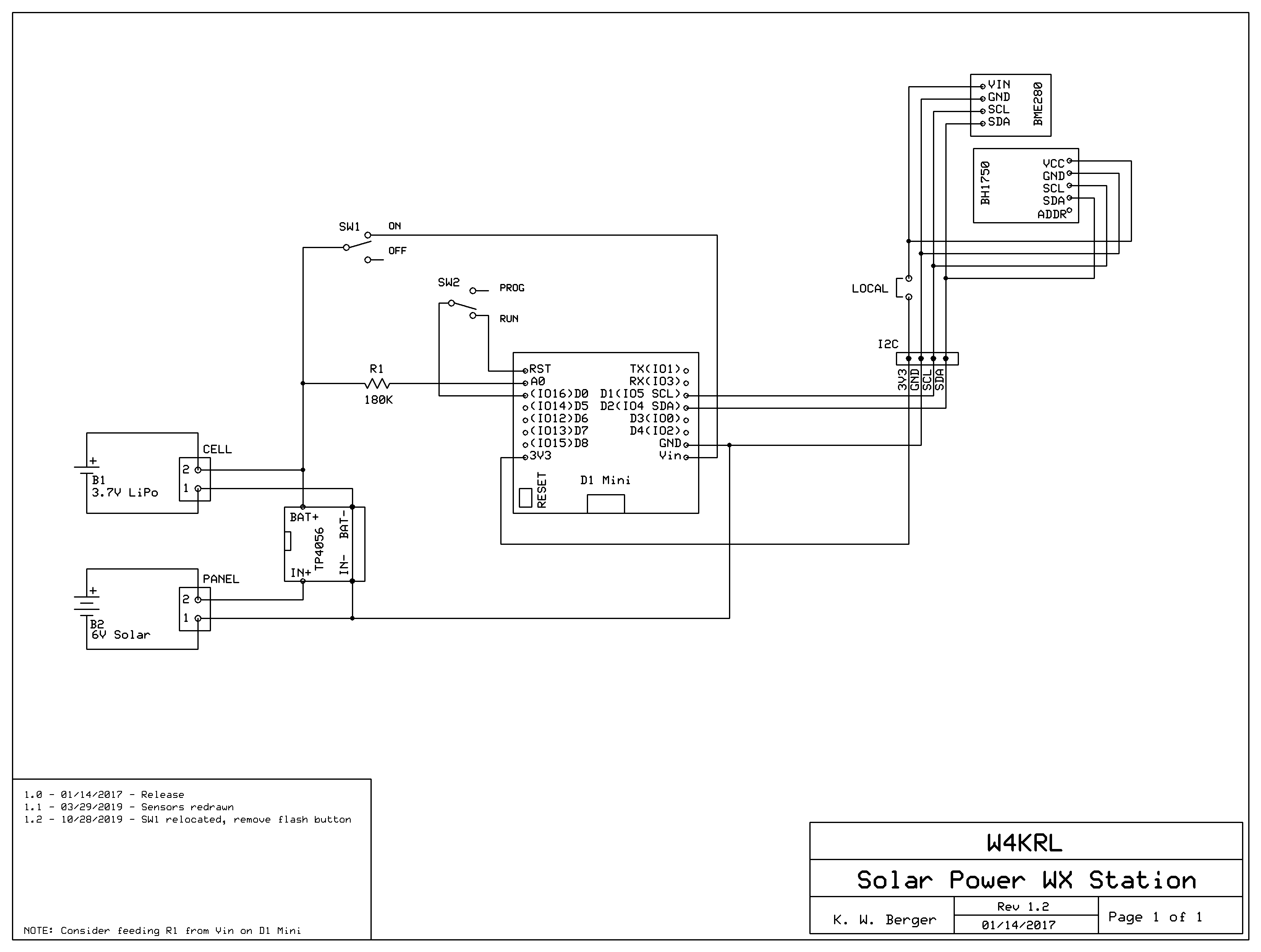
The D1M-WX1 and D1S-WX1 IoT Weather Stations use an ESP8266 System on Chip microcontroller to read and interpret weather data from sensors, format the data so that it is understandable by online services, and transmit the data to the Internet over Wi-Fi. The unit is completely solar-powered. A lithium polymer cell maintains operation in darkness.
Power Supply
Solar energy derived from sunlight is converted into electrical energy by a solar panel. The panel is composed of a series string of silicon photovoltaic cells. In bright sunlight, the panel produces 6 volts at up to 100 mA.
To continue operation at night and on dark days, a lithium polymer cell stores excess electrical energy when available. A TP-4056 charger regulates the solar-generated electrical power to maintain the charge without overcharging the cell.
The ESP8266 microcontroller operates when supplied with voltage between 3.0 and 3.5 V DC. A fully charged cell has a terminal voltage of about 4.2 V DC that gradually drops to 3.0 V DC as energy is consumed. The D1 Mini breakout board includes a voltage regulator that supplies the microcontroller with 3.0 to 3.3 V DC from an input voltage in the range of 3.1 to 10 V DC connected to the VIN pin on the D1 Mini. When the lithium polymer cell is connected to this terminal, the cell will safely supply the D1 Mini. The 3.3 V DC output of the D1 Mini regulator is connected to the 3V3 pin. A limited amount of current may be drawn from the 3V3 pin to supply the sensors with electrical power.
Switch SW1 is the power switch for the station. When in the ON position, the cell is connected to the D1 Mini. In the OFF position, the cell can be charged with solar power or with power drawn from a USB supply connected to the micro USB jack on the TP4056 breakout board.
The D1 Mini can also be powered through its micro USB jack. NOTE: If you power the D1 Mini through its USB port set SW1 to OFF to prevent backfeed to the LiPo cell.
ESP8266 System on Chip
The ESP8266 is a powerful microcontroller that incorporates a Wi-Fi transceiver, flash memory, and other supporting components. It is a surface-mount device (SMD) that requires a few additional components to function in the weather station. Two important supporting components are the voltage regulator previously described and a USB adapter. These and other components are mounted to the backside of the D1 Mini breakout board.
The main function of the USB adapter is to convert signals to and from a PC to RS-232 (EIA-232) serial signals used by the ESP8266 for programming and communication. Additional components enable the USB chip to control the programming and operating state of the ESP8266.
The ESP8266 is supplied with a firmware LUA interpreter. LUA is an interesting computer language that does not yet have the wide support enjoyed by the Arduino flavor of C++. Fortunately, a dedicated band of programmers has developed an ESP8266 core. When the core is loaded into the Arduino Integrated Development Environment (IDE) it enables programming the ESP8266 exactly like it was an Arduino. This makes the huge Arduino ecosystem available to users of the ESP8266.
Deep Sleep
One of the many interesting features of the ESP8266 is its ability to go into a very low power mode called deep sleep. This is an important feature for the weather station since it relies upon the limited energy available from the lithium polymer cell during periods of darkness.
Measurements show that the D1 Mini and the weather sensors draw around 80 µA when in deep sleep; a very small amount of current. However, in the six to ten seconds the station is transmitting data to the Internet, it may draw up to 300 mA with an average of about 80 mA. If the sleep mode was not available, the station would require a much larger solar panel and storage cell.
When in deep sleep, the only active part of the ESP8266 is an internal real-time clock (RTC). The weather station firmware sets the RTC to wake up the ESP8266 after ten minutes of deep sleep. When the sleep interval has expired, the RTC pulls pin D0 to ground. To wake up the processor, the reset pin RST must be pulled to ground. When the RUN/PROG switch is in the RUN position, the reset signal from D0 is connected to the RST pin and the chip will wake itself up every ten minutes. Unfortunately, pin D0 is also used by the USB adapter to control the programming of the ESP8266 and would be affected by the RTC reset function. When the switch is in the PROG position, the connection between D0 and RST is opened allowing normal programming of the chip. It is important to return the RUN/PROG switch to the RUN position after programming.
I2C Interface Bus
Data and control information is exchanged between the sensors and the microprocessor over an I2C serial bus. I2C stands for Inter-Integrated Circuit and is pronounced “eye-squared cee”. The I2C bus is ideally suited for the relatively low data rates needed for weather measurements and needs only two data pins on the D1 Mini. The software drivers for the I2C bus are built in to the Arduino software making it very easy to connect compatible I2C sensors to the microcontroller. Each I2C device must have a unique address. Some devices allow selection of the address and some do not. The sensors used in this weather station have fixed addresses. The driver library software for the BME280 and BH1750 have the addresses hard coded.
I2C Expansion Header
The D1M-WX1 has a 4-pin header marked I2C on the printed circuit board to provide for remote sensors or the addition of other I2C devices.
Each I2C device must have a unique address. In some cases, the address is selectable by the user. This is not the case with the BME280 and BH1750 sensors. The onboard sensors must be disabled if remote BH1750 and BME280 sensors are added. Address conflict can be avoided by removing power to the onboard sensors. This is easily done by removing the shunt jumper from the 2-pin LOCAL header.
BME280 Environmental Sensor
The BME280 Environmental Sensor by Bosch Sensortech is a high accuracy sensor for pressure, temperature, and humidity. These are the primary weather parameters measured by the station.
The actual device is in a metal package 2.5 mm square and less than 1 mm thick. The breakout board requires just four wires: VIN and GND for power, and SCL and SDA for the I2C serial bus.
The measurements made by the BME280 are linear, floating point values. As with most sensors, the measurement units are metric and may be converted to US units by simple mathematic routines.
Generally, the placement of the weather station will not affect pressure and humidity measurements. Temperature measurements may be affected by solar heating of the weather station enclosure. If you notice unrealistically high temperatures during the day, you may wish to relocate your station so that direct sunlight does not fall on it. Good ventilation above and below the station is also important.
BH1750 Light Intensity Sensor
The BH1750FVI Ambient Light Sensor by ROHM Semiconductor is an I2C device with a spectral response very similar to the human eye. Unlike the eye, however, its amplitude response is linear rather than logarithmic. Its range of 0 to 65,535 lux responds to intensities from cloudy moonlight to medium bright sunlight. This is adequate to provide a relative measure of the brightness of cloudy and sunny days.
The light intensity measurement is strongly affected by the location of the weather station. Useful measurements can be obtained by a station not in direct sunlight. As with most light sensitive devices, the angle of incidence of the light strongly affects the measurement. This means that light from directly over the sensor will register a higher intensity than light coming from an angle. This is similar to the heating effect of sunlight on the earth and accounts for winter being colder than summer.
Charge Monitor
In addition to weather data, the station reports the lithium polymer cell voltage to provide an indication of the state of the charge. The voltage is measured using the analog to digital converter (ADC) built into the ESP8266. The ADC has a range of 0 to 1 Volt that is reported as a 10-bit digital value from 0 to 1023. Since the cell voltage may exceed 4.2 V DC at full charge, it is necessary to use a voltage divider to reduce the voltage applied to the ESP8266. The D1 Mini has a voltage divider composed of a 220 kilohm resistor and 100 kilohm resistor that increases the range to 0 to 3.2V DC. The station adds an external 180 kilohm resistor (R1) to further increase the range to 5 V DC.
While all three voltage divider resistors are precision devices, an optional calibration step is provided in the D1M-WX1 kit to ensure good accuracy.
Received Signal Strength Indicator
The Received Signal Strength Indicator (RSSI) is a function built into the Wi-Fi receiver of the ESP8266. RSSI is a measure of the power level of the Wi-Fi signal from your access point. There is no standard for the accuracy of the RSSI value, however, it is common (whether accurate or not) to show the value as decibels referenced to a milliwatt written as dBm. Since the received power is very small, the RSSI is a negative value when given in dBm. The closer the figure is to zero, the better. As a general example, a good signal would be -50 dBm, a reasonable strength would be -75 dBm, a bad one would be 90 dBm, and 100 dBm would provide no service at all.
The weather station reports the RSSI to help you judge how reliable the Wi-Fi signal is at the station location. It may also be an interesting experiment to see if there is a relationship between signal strength and weather conditions. For example, higher humidity may reduce signal strength.