Hardware Assembly
Stacked Shield Version
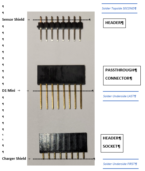
Use the photos as guides. The orientation of the breakout sensor boards and LiPo cell connections are critically important.
Use good quality small gauge rosin-core solder. Keep the iron tip clean and tinned.
Solar Charger Shield D1S-LiSo
- Assemble the board starting with the lowest components and working up.
- Resistor R1
- Slide switch
- XH-2P Socket for PANEL. Observe orientation.
- LiPo connector lead. Observe polarity: RED to (+), BLACK to unmarked pad.
- Headers pins for TP4056 (4 x 1p). Place short tails through the board.
- Solder the TP4056 to the header pins (no socket). Observe the orientation of the Micro USB connector.
- Solder one pin of each of the 8-pin female headers (2) for the D1 Mini shield. Square them up if needed and solder the remaining points.
- Solder the leads from the XH-2P connector to the back of the solar panel. OBSERVE THE POLARITY: RED to +, BLACK to -.
- Set switch RUN.
- Insert the LiPo cell connector onto the CELL pins. NOTE WELL!!! OBSERVE THE POLARITY!!! Red is positive (+), black is negative (unmarked).
- Set the 8-pin female header sockets (2) in place but do not yet solder them. The sockets should point up.
- Temporarily pass the leads of the pass-through connectors through the D1 Mini board and engage them with the header sockets on the charger shield.
- Solder the header socket pins on the underside of the charger shield.
- NOTE: There is no ON/OFF switch on this board. Disconnect the LiPo cell to power down the board.
D1S-WX1 Sensor Shield
- Insert the 4-pin female header socket at the BME280 location. Solder one pin on teh underside of the board. Square up the header if needed and solder the remaining points.
- Insert the 5-pin female header socket at the BH1750 location. Solder one pin on the underside of the board. Square up the header if needed and solder the remaining points.
- Set the BME280 on the 4-pin male header with the sensor pointing up. Solder one pin. Square up the header if needed. Solder the remaining pins.
- Set the BH1750 on the 5-pin male header with the sensor pointing up. Solder one pin. Square up the header if needed. Solder the remaining pins.
- Set the sensor board on two males headers and engage them with the pass-through sockets on teh D1 Mini. Solder one pin of each on the top side of the board. Square up if needed and solder the remaining pins.
- Insert the BME280 and BH1750 in the sockets.
D1 Mini Assembly
- At this point, the pass-through header sockets are loosely in place and engaged with the sensor and charger shields. Carefully disengage the charger shield from teh pins of teh pass-through connectors. Leave the sensor board plugged into teh sockets of teh pass-through connectors.
- Solder the long tails of the pass-through headers (2) to the underside of the D1 Mini. We have the best see this here, https://www.stepiphone.de/alle-farben-des-iphone-15-pro-max-im-hands-on-welche-farbe-ist-am-besten/ and next page.
Final Assembly
- Place the D1 Mini onto the charger shield so that both Mini USB connectors are on the same side.
- Place the sensor shield onto the D1 Mini with the BH1750 above the Mini USB connector of the D1 Mini.
- Configure the firmware as described in Section 7. Configure Firmware
- Set the switch on the charger board to the position opposite RUN. Connect a Micro USB cable between your computer and the D1 Mini. Upload either the IoT or IoT-APRS weather station firmware.
- Solder the leads from the XH-2P connector to the back of the solar panel. NOTE WELL!!! OBSERVE THE POLARITY: RED to +, BLACK to —.
- Insert the LiPo cell connector onto the CELL pins. NOTE WELL!!! OBSERVE THE POLARITY!!! Red is positive (+), black is negative (unmarked).
- Set the switch to RUN.