The ESP32 is a powerful microcontroller with many input/output ports. Specifically, it contains two 12-bit multiplexed analog to digital converters (ADCs) for a total of 18 channels. ADC1 is attached to eight GPIOs from 32 to 39. ADC2 is attached to 10 GPIOs (0, 2, 4, 12 to 15 and 25 to 27). There are some restrictions on the use of ADC2 when the WiFi transceiver is active. Since most applications are WiFi-enabled, it is best to use ADC1 when possible.
The 12-bit resolution of the ADC maps the input voltage from 0 to 3.3 Vdc to byte values of 0 to 4,095. Unfortunately, the ADC converters exhibit non-linear characteristics. There is a lower threshold voltage of about 0.13 volts before the ADC starts to register and the volts per bit ratio above about 2.5 volts deviates from the nearly linear ratio between these two regions.
Some careful measurements on a doit.com DevKit v1 obtained the results in Table 1. Figure 1 clearly shows the non-linearities at the lower and upper ends of the input voltage.

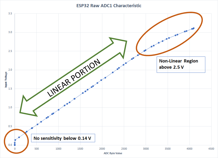
By inspection, the ADC has better than 3% accuracy on the input range of 0.14 to 2.6 volts corresponding to ADC output byte values of 100 to 3000. Between 0.21 and 2.53 V the accuracy is better than 1%. Fitting a linear equation to the 1% range produces this relationship:
Vin = 0.0008 * byte + 0.1372 (volts)
Figure 2 shows the entire characteristic of the ADC when compared with the fitted curve. It is clear that the ADC is not usable below 0.13 volts and inaccurate above 2.5 volts.

The next step is to fit another equation to ADC values above 3000:
Vin = 0.0005 * byte + 1.0874 (volts)
Figure 3 shows that these two “piecewise linear” equations produce better than 1% accuracy from 0.14 volts to 3.1 volts.

Code to implement this is easy:
const int PIN_VBAT = 34;
float volts = 0;
int adc = 0;
adc = analogRead( PIN_VBAT );
if ( adc > 3000 )
{
volts = 0.0005 * adc + 1.0874;
}
else
{
volts = 0.0008 * adc + 0.1372;
}
As a practical matter, it is wise to filter the ADC output to remove noise and jitter. There are some nice Arduino libraries to do this but it is quite straightforward to just sum a bunch of readings and take an average. Here is the complete code with the two fitted equations, filtering, and scaling described below:
const int PIN_VBAT = 34; // can use pins 32 to 39

// input voltage scaling, see
// http://jansson.us/resistors.html
const float VL = 3.11;   // max value of ADC input
const float VH = 50.0;   // max range of input voltage

setup()
{
  Serial.begin(115200);
}

loop()
{
  float volts = 0;
  int adc = 0;
  long adc_sum = 0; // must be long to hold a large value

// read and accumulate the ADC value 10 times
  for ( int i = 0; i < 10; i++ )
  {
    adc = analogRead( PIN_VBAT );
    adc_sum = adc_sum + adc;
  }

// divide by the number of readings to get the average
  adc = adc_sum / 10;

// calculate the voltage using the averaged ADC
  if ( adc > 3000 )
  {
    volts = 0.0005 * adc + 1.0874;
  }
  else
  {
    volts = 0.0008 * adc + 0.1372;
  }
// add any voltage scaling here
  volts = VH * volts / VL;

  Serial.print(“Vin = “); Serial.println( volts );
}
Scaling
If you want to measure an input voltage above the natural 3 volt range of the ADC you must add a resistor voltage divider to the ESP32 ADC input. You can find formulas to do this on the Internet but there is an excellent online calculator at http://jansson.us/resistors.html. Here are steps to designing a divider for a 50-volt input:
- Navigate to http://jansson.us/resistors.html.
- Select the resistor series. Resistors in the E12 series are the cheapest and most available.
- Find the calculator for “Resistor Ratio” and select the Voltage Divider radio button.
- For the maximum input voltage enter 50 for VH.
- For the maximum output voltage enter 3.11 for VL. This seems to be the maximum input voltage for the ESP32 corresponding to ADC output of 4,095.
- Press the Calculate button. The result is a resistor ratio of 15.077170418006432 to 1.
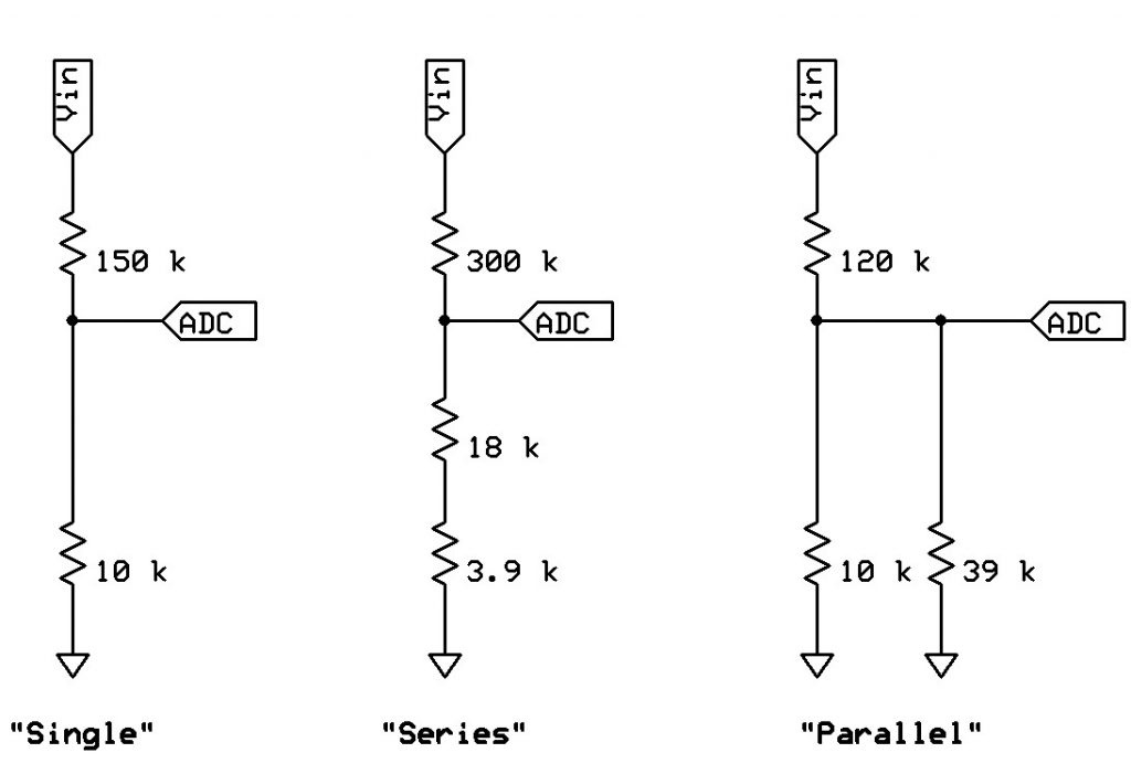
- The calculator provides three possible solutions:
a. Single: a 150 kΩ in series with 10 kΩ. This is a ratio of 15:1 which is within 0.51% of the desired ratio.
b. Series: a 300 kΩ resistor in series with the series combination of 18 kΩ and 3.9 kΩ. This is within 0.06 % of the desired ratio.
c. Parallel: a 120 kΩ resistor in series with the parallel combination of 10 kΩ and 39 kΩ. This is an exact solution. - Add a line to the code to change the scale of the voltage (note that 50.0 is the VH value and 3.11 is the VL value as used in the Resistor Ratio calculator):
volts = 50.0 * volts / 3.11;

Any of the three voltage divider circuits shown in Figure 4 can be used depending upon the resistor values that are available to you.